


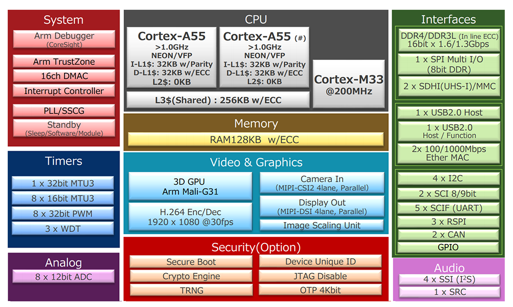
? 瑞萨RZ/G2L是通用处理器中接口最全面的MPU之一,将稳定供货至少10年以上。其工作温度满足-40℃~+85℃,适用于电力、医疗、轨道交通。工业自动化、环保、重工等多行业领域。该处理器搭载双核Cortex-A55@1.2GHz+Cotex-M33@200MHz,集成3D图形加速引擎,ARM?Mail-G31(500MHz);支持OpenCL2.0、OpenGL?ES1.1/2.0/3.0/3.2,支持1080P高清显示与H.264视频硬件编解码。
RZ/G2L is one of the most comprehensive interfaces in the generic processor and will stabilize its supply for at least 10 years. Working temperature meets -40°C~+85°C and applies to power, medical, orbital transport. Industry automation, environmental protection, heavy work, etc. multi-industry areas. The processor carries a double-nuclear Cortex-A55@1.2GHz+Cotex-M33@200MHz, integrated into a 3D graphical acceleration engine, ARM? Mail-G31 (500 MHz); supports OpenCL 2.0, OpenGL?ES1.1/20/3.0/3.2, supports 1080P high-cleaning display decoding with H.264 video hardware.
? 万象奥科G2L核心板采用瑞萨RZ/G2L作为核心处理器,该处理器搭载双核Cortex-A55+Cotex-M33处理器,集成高性能Mail-G31?GPU,适用于工业控制、人机交互、数据网关、边缘计算等多种应用场景。本此将使用HDG2L-IOT评估板/开发详细测评G2L的功能、性能。
The VOICEO G2L core board uses RZ/G2L as its core processor, which carries a double-nucle Cortex-A55+Cotex-M33 processor that integrates high performance Mail-G31?GPU, which applies to a variety of applications such as industrial controls, human interfaces, data gateways, and margin computing. This will use the HDG2L-IOT assessment board/developing a detailed assessment of G2L functionality and performance.
?
图1?RZ/G2L处理器架构
?
? 了解了一些预备知识后,我们进入正题,HDG2L-IoT开发板开箱!
♪ After learning some preparatory knowledge, we're getting to the point where the HDG2L-Iot development board opens!
? 开发板采用常见的环保纸盒进行包装,包装盒内采用防碰撞缓冲保护设计,可以很好的保护产品,这款开发板也使用了珠光膜气泡袋进行包装,防水防震的PE材质全方位保护产品,内部也使用了可回收利用的防静电网格袋,如图2所示。
• The development board is packaged using common environmental paper boxes, which are designed for collision-proof buffer protection and can well protect products. The development board is also packaged using bead film bubble bags, the water-proof PE material is protected in all its aspects, and recyclable electrostatic grid bags are used internally, as shown in figure 2.
?

图2?整体包装
? 开发板整体为邮票孔核心板+工控板的设计方式,工控板整体机械尺寸为180mm*120mm,核心板整体机械尺寸为70mm?*?45mm,工控板四角预留了4个安装孔位,正反面如图3图4所示。
• The development board as a whole is the design of the stamp hole core board plus the engineering control board, which has an overall mechanical size of 180 mm*120 mm, and the core board, which has an overall mechanical size of 70 mm?*45 mm, with four installed holes reserved for the four corners of the board, as shown in figure 3, figure 4.
?

图3?开发板正面
?
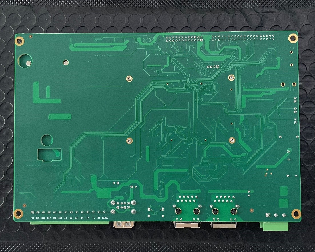
图4?开发板背面
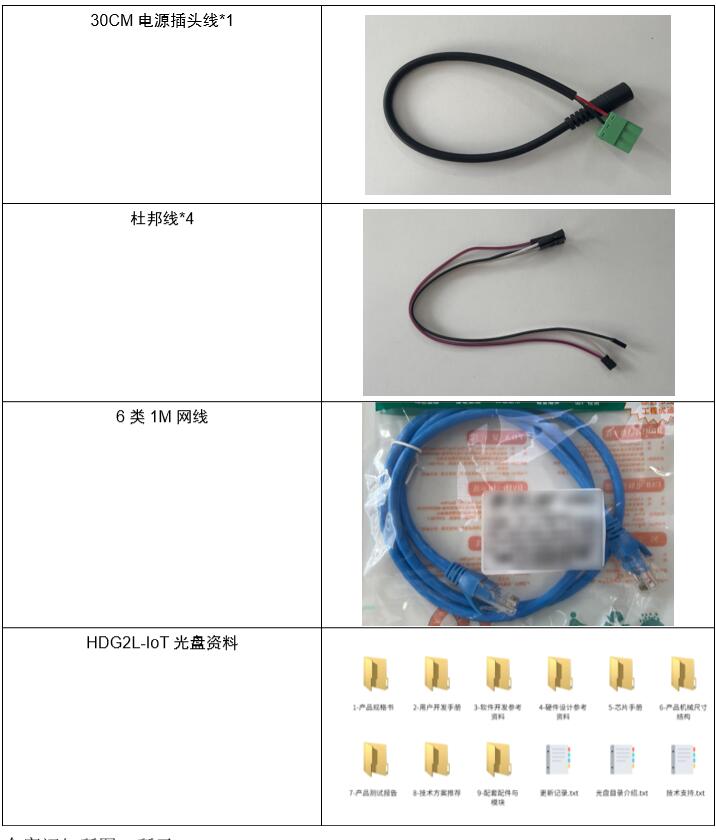
? HDG2L-IoT开发板主要包括以下配件,如表1?配件所示。
• The HDG2L-IOT development board consists mainly of the following accessories, as shown in table 1?
表1?配件
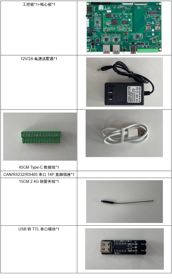
全家福如所图5所示。
The family is blessed as shown in figure 5.
?

图5 全家福
? 对于初学者入门学习来说,完全够用,当然用户也可以选择搭配电阻屏&电容屏进行可视化操作。更多设备型号可参考我公司淘宝店铺(芯路遥电子),或扫描下方二维码直达店铺。
More equipment models can be found in my company’s treasure-hunting shop (core remote electrons) or scanning down two-dimensional lines straight to the shop.
?

HDG2L-IoT核心板主控选用RZ/G2L?MPU,板载1GB或2GB高速DDR4内存、8GB或更高?eMMC(支持定制)。核心板支持运行精简Linux、Ubuntu、Android操作系统,提供完善且健壮的外设驱动支持,旨在帮助用户快速应用RZ/G2L平台,实物图如图6所示。
The HDG2L-IOT core board, which is controlled by RZ/G2L?MPU, carries 1GB or 2GB high-speed DDR4 memory, 8GB or higher?eMMC (supports customization). The core board supports the operation of streamlined Linux, Ubuntu, Android operating systems, providing sound and robust external drivers to help users quickly apply RZ/G2L platforms, as shown in figure 6.
?

图6?核心板
? RZ/G2L核心板集成千兆网口、CAN-FD、UART、USB等接口,并支持网口、CAN、串口功能扩展。集成8通道12位ADC、8路32位PWM(支持脉冲输入捕获)、多路SPI与IIC,支持看门狗与OTP单元(可用于授权加密)。
The RZ/G2L core boards are integrated into gigabytes of portals, CAN-FD, UART, USB, etc., and support the network portal, CAN, serial function extension. Integrator 8 channels 12 ADCs, 8 routes 32 PWMs (support for pulse input capture), multiple routes SPI and IICs, and support the gate dog and OTP modules (which can be used for authorized encryption).
? RZ/G2L核心板硬件参数如表2所示。
The RZ/G2L core plate hardware parameters are shown in table 2.

表2?核心板参数
下面来看一下核心板的细节实拍图,如图7所示。
The details of the core plate are shown below, as shown in figure 7.
?

图7?核心板细节图
? HDG2L-IOT基于HD-G2L-CORE工业级核心板设计,双路千兆网口、双路CAN-bus、2路RS-232、2路RS-485、DSI、LCD、4G/5G、WiFi、CSI摄像头接口等,接口丰富,适用于工业现场应用需求,亦方便用户评估核心板及CPU的性能。
• HDG2L-IOT is based on the design of the HD-G2L-CORE industrial core board, which consists of a two-way gigabytes portal, a two-way can-bus, a two-way RS-232, a two-way RS-485, DSI, LCD, 4G/5G, WiFi, CSI camera interfaces, etc., with a rich interface that applies to industrial field application needs and allows users to assess the performance of the core plate and CPU.
? HD-G2L-CORE系列工业级核心板基于RZ/G2L?微处理器配备?Cortex?-A55?(1.2?GHz)?CPU、16?位?DDR3L/DDR4?接口、带?Arm?Mali-G31?的?3D?图形加速引擎以及视频编解码器?(H.264)。?此外,这款微处理器还配备有大量接口,如摄像头输入、显示输出、USB?2.0?和千兆以太网,因此特别适用于入门级工业人机界面?(HMI)?和具有视频功能的嵌入式设备等应用。实物图如图8所示。
The HD-G2L-CORE core plate is based on RZ/G2L? Microprocessors? Cortex?-A55?(1.2?GHz)?CPU, 16?bit?DR3L/DDR4? interfaces?Arm?Mali-G31?? 3D? Graphical acceleration engines and video codecers? (H.264.) In addition, the microprocessor is equipped with a large number of interfaces, such as camera input, display output, USB?2.0? and gigabyte web, and is therefore particularly suitable for applications such as portal industrial interfaces? (HMI)? and embedded devices with video functions.
?

图8?HDG2L-IoT开发板
HDG2L-IoT板载的外设功能:
External features on HDG2L-IOT board:
集成2路10M/100M/1000M自适应以太网接口
Integrating 10M/100M/1000M self-adapted Ether web interface
集成Wi-Fi
Integrated Wi-Fi
集成2路RS-232接口
RS-232 interface integrated 2
集成2路RS-485接口
Integrated 2-way RS-485 interface
集成2路CAN-bus接口
Can-bus interface integrated 2
集成2路USB?Host
U.S.B.? Host?
集成1路USB扩展4G模块接口(集成SIM卡接口)
USB Extension 4G Module Interface on Integrated Track 1 (Integration SIM Card Interface)
集成1路USB扩展5G模块接口(集成SIM卡接口)
USB Extension 5G Module Interface on Integrated Track 1 (Integration SIM Card Interface)
支持1路TF卡接口
Support for TF card interface on track 1
支持液晶显示接口(RGB信号)
Support LCD interface (RGB signal)
支持4线电阻触摸屏与电容屏接口
Support 4-line electroresistance screen interface with capacitor screen
1路MIPI?DSI接口
1-way MIPI? DSI interface.
1路摄像头接口(MIPI?CSI)
1-way camera interface (MIPI?CSI)
支持音频(耳机、MiC、SPK)
Support audio (earphones, MiC, SPK)
支持实时时钟与后备电池
Support real-time clocks and back-up batteries
支持蜂鸣器与板载LED
Support beeper and board LED
支持GPIO
Support GPIO
1路TTL调试串口
Track 1 TTL Debug Serial
直流+12V电源供电(宽压9~36V)
Direct current + 12V power supply (9~36V)
?
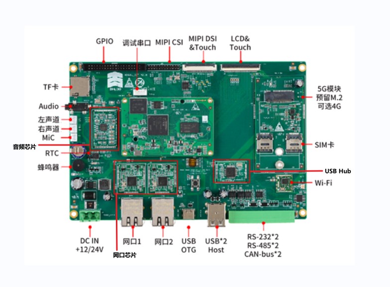
图9?HDG2L-IoT开发板接口布局图
?
? HDG2L-IoT系列核心板配套有数10G开发资料,通过网盘可随时下载,涵盖文件系统及内核源码、用户开发说明书、硬件设计参考电路、外设接口应用范例等技术文档。针对深度开发的用户,万象奥科可提供专属微信服务群组,协助深度定制驱动及内核系统。
The HDG2L-IOT core board is equipped with 10G development materials, which can be downloaded readily via web disk, covering document systems and technical documents such as kernels, user development instructions, hardware design reference circuits, and examples of external interface applications.
?

图10?配套资料

图11?部分用户手册目录
注:万象奥科官方网站:http://www.vanxoak.com/?
Note: Vientiane Oco official website: http://www.vanxoak.com/?
? 经过一系列的资源了解后,我们根据用户开发手册第十章节系统恢复与更新教程将内核和文件系统烧录至开发板后就可以正常使用了,此处不再赘述。
After a series of resources, we can use the kernel and file systems properly when they are burned to the development board in accordance with the user development of chapter X of the manual. This is not repeated here.
? 篇幅有限,本文仅演示部分功能与接口测试数据,如需详细功能与接口测试数据,可访问万象奥科官方网站获取。
# Limited space, only some of the functional and interface test data are shown here, and if detailed functionality and interface test data are required, they can be accessed on the official Vientiane Oco website.
连接调试串口位置如图12所示,该串口位于核心板上方。
The location of the debug link is shown in figure 12, which is above the core plate.
?

图12?调试串口
? 使用串口线连接HDG2L-IoT和PC机时,首先确认连接电脑的串口端口号,从“设备管理器”中查看串口端口号,以电脑识别的端口号为准。若拔插仍然没有端口号,可尝试重新启动PC,再次连接。
# When connecting to HDG2L-Iot and PC machines with a serial port number, first confirm the serial port number that connects to the computer and check the serial port number from the Device Manager, depending on the computer-recognized port number. If you still do not have the port number, try to restart the PC and connect again.
?

图13?串口号
? HDG2L-IoT的基本硬件资源了解完之后,我们可以对开发板进行上电启动,简单测试一下开发板的硬件功能是否正常。
After learning about the basic hardware resources of HDG2L-Iot, we can power the development board and simply test the hardware functionality of the development board.
? 测试环境:
♪ Test environment:
? 1.操作系统,windows?11家庭中文版。
♪ 1. Operating systems, Windows ♪ 11 family Chinese version. ♪
? 2.终端工具,MobaXterm。
♪ 2. Terminal tool, MobaXterm.
? 3.硬件工具,HDG2L-IoT开发板、Type-C数据线、12V/2A电源适配器。
3. Hardware tools, HDG2L-IOT development panels, Type-C data lines, 12V/2A power adapter.
? 4.硬件设置,开发板已烧写内核文件系统,拨码设置0100?EMMC启动。
4. Hardware set-up, development board burned kernel file system, dial-up 0100?EMMC activated.
? 将数据线连接至电脑,并将Type-C口连接到USB串口模块,再将杜邦线连接至开发板的调试串口和USB串口模块,最后使用配套的12V/2A电源适配器,连接电源线后将电源直角插座连接到开发板的DC电源口,此时会看见开发板电源、运行LED灯亮起并伴随滴的一声完成开机。
• Connect the data lines to the computer and connect the Type-C to the USB Serial Module, then connect the Dubon Line to the debugging and USB Serial modules of the development board, and finally use the accompanying 12V/2A power adapter to connect the power lines to the DC Source of the development panel, at which point an opener will be seen to develop the power source, run the LED light and drop with it.
? 接线图如图14所示。
The route map is shown in figure 14.
?
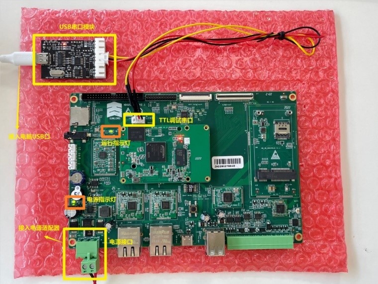
图14?接线图
? 本处使用配套资源的MobaXterm软件演示,查看开发板完整的启动信息,操作如下所示:
The Service uses the MobaXterm software demonstration of the supporting resources to view the full start-up information of the development board, as follows:
? 1.开发板正确启动。
1. The development board is properly activated.
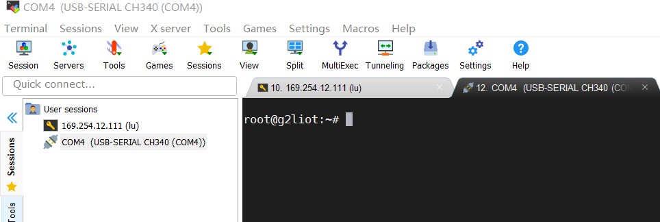
? 2.打开电脑设备管理器查看端口号为COM4。
? 2. Open the computer device manager to see port number COM4.
? 3.打开MobaXterm软件,本处使用Serial登录,操作如下图15所示。
? 3. Open the MobaXterm software and use the Serial login here to operate as shown in figure 15 below.

?
图15?开发板启动步骤
? 4.然后回车,输入账号root继续回车即可成功进入开发板,这时我们输入reboot重新启动开发板就可以查看到开发板启动信息了,如图16所示。
♪ 4. Then return to the vehicle and enter the account root to continue to enter the development board successfully, so that we can enter the reboot restart development board and see the start-up information on the development board, as shown in figure 16.
?

图16?启动信息
? 若需查看CPU信息,如读取内核数、主频、CPU工作温度可使用如下指令:
If you need to see CPU information, e. g. read kernel numbers, main frequency, CPU working temperature, the following instructions can be used:

? 注:更多指令可查看第九章节《常用指令》
# Note: More instructions can be viewed in chapter IX: Common Instructions
? ?控制LED灯亮灭指令如下:
♪ Controlled LED lights out as follows:

?
? ?开发板LED灯亮灭图如图17所示:
♪ The development board LED lights are on-line as shown in figure 17:
?

图17?LED亮灭示意图
? 除了基础的亮灭操作以外,有编程基础的小伙伴还可以写一个脚本程序,来控制LED灯定时闪烁。
• In addition to the underlying extinguishing operation, small partners with programming bases can write a script program to control LED lamps for time-scining.
? DDR读写指令如下:
♪ The DR reads and writes with the following instructions:

? 界面显示如图18所示。
The interface is shown in figure 18.
?

图18?DDR读写示意图?
? HDG2L-IoT开发板标配两个以太网口,分布如图19所示。
* The HDG2L-Iot development board is marked with two ultranets distributed as shown in figure 19.
?

图19?以太网接口
? ? 默认情况下,ETH0配置为静态IP,ETH1配置为动态IP,本处使用ETH0接口演示。
♪ By default, ETH0 is configured as static IP, ETH1 is configured as dynamic IP, and this place uses the ETH0 interface to demonstrate.
? ? 调试阶段内,需使用网线将开发板与PC连接,并保持PC端与HDG2L-IoT开发板在同一网段内,操作步骤如下:
During the debugging phase, the development board needs to be connected to the PC using a web line and to maintain the same PC end as the HDG2L-Iot development board in the same network segment, with the following operational steps:

? 设置PC端以太网IP地址。
# Set up the PC-end IP address for the Internet.
?

图20?设置PC端IP地址

?
图21?设置PC端IP地址
? 本例中,固定PC端的以太网口的IP地址为192.168.10.125,的eth0为192.168.10.20,两个设备在同一个网段内。设置好IP在同一网段后,可以使用PC端的CMD命令提示符测试是否PING通开发板,或使用MobaXterm?终端Ping?PC端,命令如下,实例如图22所示:
• In this case, the fixed PC-end IP address for the Pythal portal is 192.168.10.125, the eth0 is 192.168.10.20 and the two devices are in the same section. Once the IP has been set up in the same section of the network, the PING development board may be tested using the CMD hint at the PC-end, or the MobaXterm? terminal Ping?PC end command, as shown in figure 22, as follows:

?

图22?PING测试
? 部分用户会遇到设置正确仍无法进行相互ping测试,可尝试关闭电脑端的防火墙,以Windows?10为例,关闭操作如图23所示,关闭后可再次尝试ping操作。
# Some users will be confronted with the correct set-up but are still unable to ping each other, try to close the firewall on the computer end, for example Windows?10, close operations as shown in figure 23, and try to ping again after closing.
?

图23?关闭防火墙
? HD070-LCD800480液晶套件(800*480分辨率,可选1024*600分辨率)是基于群创7寸液晶开发的液晶套件,接口包含液晶屏电源输出(VLCD)、四线电阻式触摸屏接口、电容触摸屏接口,适配万象奥科各类评估主板。
* The HD070-LCD80480 LCD package (800*480 resolution, optional 1024*600 resolution) is based on the LCD package developed by a group of 7-inch LCDs, with interfaces consisting of LCD output (VLCD), four-line barrier-to-touch screen interfaces, capacitation touch screen interfaces, adapted to various evaluation panels in Vientiane Oko.
? 本文示例工业级电容触摸屏支持10点触控,支持带水触控,戴手套触控(最厚5mm的雪地手套),厚盖板触控(最厚可穿透15mm的玻璃触控),高稳定性与抗干扰性,可过国军标电子电磁兼容测试,表面硬6H以上,抗耐摔抗划伤,寿命持久度。
♪ This paper provides examples of industrial-grade capacitor touch screens that support 10 points of touch control, support water contact control, gloves touch control (the thickest 5 mm snow gloves), thick sheet touch control (the thickest glass contact control that can penetrate 15 mm), high stability and resistance to interference, pass the electromagnetic compatibility test of the State's military beacon, surface hard 6H and above, anti-falching injuries and end-of-life.
? 液晶套件由PCB背光板、液晶屏、触摸屏、铁框组成。实物正反图如图24所示。
The liquid crystal package consists of a PCB backboard, a liquid crystal screen, a touch screen, and an iron frame.
?

图24?液晶套件
? 硬件参数:
♪ Hardware parameters:
液晶显示屏
Liquid Crystal Display
真彩TFT
It's a tft.
分辨率800*480(可选1024*600)
Resolution 800*480 (option 1024*600)
26万色
260,000 colors.
点距0.1926mm*0.1790mm
Point range: 0.1926mm*0.1790mm
显示区域154.02mm(H)*85.92mm(7.0英寸)
Show area 154.02 mm (H)*85.92 mm (7.0 in)
LED背光
LED backlight
触摸屏支持四线电阻式与电容式
Touch screen supports four-line electrical resistance and capacitors
表3?规格参数

? 若用户购买了液晶套件,需要在开发板断电的情况下,通过排线连接至开发板LCD&Touch口(开发板50引脚的J14接口),接线方式如图25所示,挑开接口,将排线按所示图片正确插入排线座,即可按下排线固定板。电容屏正确连接厚启动开发板,启动后可以看到开发板与显示屏同步滚动启动信息,启动完成后,显示屏显示进入系统。
If the user purchases the LCD package, it needs to be connected to the LCD&Touch portal (the J14 interface for the development board 50-guided) in the event that the development panel is out of power, by sorting out the interface, as shown in figure 25, and inserting the row line correctly into the row seat as shown, the lower line fixed board can be pressed. The capacitation screen correctly connects the thick start development panel, it can be seen that the development board scrolls the start information in conjunction with the display screen, and the screen displays the entry system after the start is complete.
? 【注意】HDG2L-IoT开发板在启动时引导的设备树文件为g2l-iot.dtb,请依照所采用的显示方案选用表中的三个设备树之一拷贝生成g2l-iot.dtb,例如采用LCD显示方案时应cp?g2l-iot-lcd.dtb?g2l-iot.dtb,然后用拷贝生成的dtb文件引导系统启动,具体可查看用户使用手册。
[Note: The device tree file guided by the HDG2L-Iot development board at start-up is g2l-iot.dtb. Please select a copy of one of the three devices in the table to generate g2l-iot.dtb according to the display scheme used, e.gp?g2l-iot-lcd.dtb?g2l-iot.dtb, and then activate the dtb file guidance system generated by the copy to see the user manual.
?

图25?液晶套件接线图
? 本例使用的电容屏支持0~7级的液晶背光调节,可支持在不同环境下的亮度需求,若要修改液晶背光,可以通过修改”/sys/class/backlight/backlight/brightness”文件的值对液晶背光进行调整。该值的取值范围为0~?7,共8个背光级别。当设置为7时背光最亮。例如要把背光值设置为5,可在命令行下执行如下命令:
# The capacitation screen used in this case supports a level 0-7 LCD back modulation that supports the need for brightness in different settings. To modify LCD backlight, the LCD backlight can be adjusted by modifying the value of the "/sys/class/backlight/backlight/backlight/brightness" file. The value has a range of 0~7 and eight backlight levels. When set to 7 hours, the backlight is the brightest. For example, if the backlight is set to 5, the following command can be executed under the command line:

? 液晶屏显示如图26所示。
♪ The LCD screen is shown as shown in figure 26.
?

图26?背光亮度调整
? HDG2L-IOT开发板搭载了Arm?Mali-G31的3D图形加速引擎以及视频编解码器(H.264),其音视频部分应用层软件采用的是Gstreamer,该框架能够被用来处理像?MP3、Ogg、MPEG1、MPEG2、AVI、Quicktime?等多种格式的多媒体数据。而Gplay则是基于Gstreamer实现的音视频播放器,能够自动根据硬件选择合适的插件进行音视频播放,运行也十分简单。
The HDG2L-IOT development board, which carries the 3D graphic acceleration engine of Arm?Mali-G31 and the video codecer (H.264), uses Gstreamer, which can be used to process multimedia data in a variety of formats, such as MP3, Ogg, MPEG1, MPEG2, AVI, Quicktime? The Gplay is based on Gstreamer's achieved audio and video player, which automatically selects suitable plugins based on hardware for audio and video broadcasting and is simple to run.
? 1.使用gst-play播放视频
? 1. Play video using gst-play
? HDG2L-IOT开发板内置了视频示例文件,其路径为(/home/root/videos/h264-hd-30.mp4),
The HDG2L-IOT development board contains video example files with paths (/home/root/videos/h264-hd-30.mp4),
? 如需播放视频,可使用命令:
# If you want to play video, you can use command:

? 输入上述命令后,系统会自动进入播放模式,显示屏可以看到视频播放,如图27所示。
? After entering the above command, the system automatically enters the playback mode, and the screen can see the video playing, as shown in figure 27.
? 视频播放阶段,也可以输入K键查看键盘快捷键列表,进行视频的暂停,音量加减等操作。
# Video playout phase, you can also enter a K-key view of the keyboard shortcut list, pause the video, add volume to volume, etc.
?

图27?视频播放
? 确保主机与开发板通讯正常?MobaXterm?连接开发板以root用户登录。
♪ Make sure the host communicates with the development board? ♪ MobaXterm? Connection development board logs in with root users.
?
? 在对COM1&2(RS-232)?进行测试时,首先在shell界面输入serialTest?/dev/ttySC1&2?后回车,出现<start...open?/dev/ttySC1?ok.>后即可开始使用杜邦线进行短接测试,接线方式如图28所示,结果如图29所示。
♪ When testing COM1&2(RS-232)? First enter the serial Test?/dev/ttySC1&2 at the shell interface. ♪ < start...open?/dev/ttySC1?ok.> then use the dubon line for short-link tests, as shown in figure 28, and the result is as shown in figure 29.
?
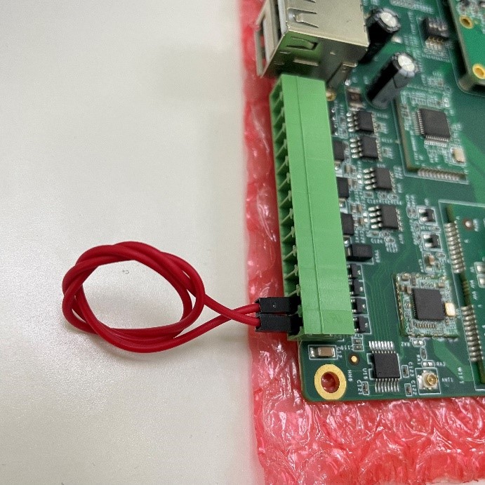
图28?RS-232短接
?

图29?RS-232测试数据
? HDG2L-IoT开发板有2个CAN口。硬件分布如图30所示。
The HDG2L-Iot development board has two CAN portals. The distribution of hardware is shown in figure 30.
?
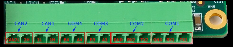
图30?HDG2L-IoT串口分布
? 查看CAN总线的状态如图31所示:
♪ Look at the state of the CAN bus as shown in figure 31:
?

图31?CAN总线状态
? 例如状态信息包括发送、接收字节,drop代表丢包数量,overrun代表一处次数,error代表总线错误次数。
# For example, status information includes sending, receiving bytes, drop represents the number of drops, overrun represents the number of errors in the bus, and error represents the number of errors in the bus.
? 在对CAN2进行测试时,确保在命令执行终端界面进入到dev文件夹内,然后在CANTest程序进行如图32红框所示设置。
? When testing CAN2, ensure that the command execution terminal interface is entered into the dev folder and then is set up in the CANTest program as shown in figure 32.
?

图32?CANTest设置参数
? 运行CANTest程序可以通过CAN口收发数据。该程序在运行时,需要提供一个命令行参数,即需要打开的CAN口名,这个CAN名参数可以为“can1”、“can2”。例如需要通过CAN2口进行数据收发,在命令行下执行如下命令:
# The CanTest program can receive and send data via the Can mouth. When running, the program needs to provide a command line parameter, i.e. the name of the can that needs to be opened, which can be used for "can1" and "can2". For example, data are sent and sent via the can2 and the following commands are executed under the command line:

? 该测程序运行流程如下:
• The application runs as follows:
打开CAN2口,其中CAN2口的通讯速率为125000。
Open the can2 and the speed of communication for the can2 is 125000.
通过CAN2口发送一个20字节的数据。
Sends a 20 byte data via the can2.
从CAN2口接收数据。
Data received from CAN2.
? 重复步骤2~3,实现数据的循环发送和接收。用户可通过CAN测试器件通过CAN总线来测试数据收发,需要设定CAN口速率为125K使两端速率匹配。图33是基于用来可电子的硬件和软件的测试显示结果。
Repeat steps 2-3, which allows data to be recycled and received. Users can test data through the CAN bus using the CAN test device, which requires a CAN oral rate of 125K to match the two-end rate. Figure 33 is based on the results of the tests for hardware and software that can be used electronically.
?

图33?数据收发?
? 武汉万象奥科RZ/G2L核心板支持2路千兆以太网接口,评估测试RZ/G2L双网口实际传输速率。
• The Wuhan Van Orco RZ/G2L core board supports the two gigabyte network interface and evaluates the actual transmission rate of the two RZ/G2L portals.
? 网口采用iperf工具进行测试,client端显示发送速率,server端显示接收速率。
♪ The web portal is tested using an iperf tool, the clieent end shows the speed of delivery and the server end shows the rate of reception. ♪
? 2.移植iperf到开发板
♪ 2. Transplant iperf to the development board
? RZ/G2L开发板上默认已集成iperf工具,无需进行移植和安装
? the RZ/G2L development board default has been integrated into the iperf tool and does not require transplantation and installation
? 3.用户主机ubuntu下安装iperf
♪ 3. Installation of iperf under user host ubuntu
? ubuntu系统可执行apt命令进行安装。
The ubuntu system can be installed with an apt command.

? 1.查看虚拟机与开发板IP地址
♪ 1. View virtual machines and development panel IP addresses
?

图34?虚拟机?开发板IP地址
? ? 2.登陆开发板作为客户端
♪ 2. Landing development board as client
? 开发板做客户端,开启iperf服务器模式:
♪ Develop board as client, turn on iperf server mode: ♪

? 3.用户主机ubuntu作为服务端
♪ 3. User host ubuntu as server

? 4.eth0测试结果
♪ 4.eth0 test results
?

图35?etho下载带宽
? 5.eth1测试结果
♪ 5.eth1 test results

?
图36?eth1下载带宽
? 基于RZ/G2L核心板设计的HDG2L-IoT开发板,两路千兆网口实测基本达到1000Mbps的最大速率。
• The HDG2L-IOT development board, based on the RZ/G2L core board design, provides a two-way gigabyte portal with a near maximum speed of 1,000 Mbps.
? 注:千兆以太网接口分别采用Microchip与裕太PHY芯片进行了测试,速率相近。?
Note: Microchip and Xuta PHY chips have been tested separately at a rate similar to that of the Giga Ether interface.
? 评估测试RZ/G2L核心板环境适应性,测试低温启动、高温工作、高低温循环状态下的工作情况。
• Assess the environmental adaptation of the RZ/G2L core plate and test the performance of low-temperature start-up, high-temperature work, high-temperature cycling.
? 2套RZ/G2L开发板HDG2L-IoT、网线、调试串口工具,电脑主机。
♪ 2 RZ/G2L development board HDG2L-IOT, web line, debugging serial port tools, computer hosts.
? 高低温试验箱。
♪ High-temperature test box.
? 注:+85℃高温测试CPU需安装散热片,45mm*45mm参考。
Note: +85°C high temperature test CPU is required to install radiant tablets, 45 mm*45 mm reference.
? 1.-40℃低温启动
? 1.-40°C cryogenic start
? 将环境温度设置-40℃,被测试样机低温存储2小时,2小时后上电启动,如图37所示。
• Set the ambient temperature - 40°C, stored in a test prototype for 2 hours at a low temperature, and powered in 2 hours, as shown in figure 37.
?

图37?环境温度-40℃
? 上电后RZ/G2L核心板启动正常。此时环境温度-40℃,通过电脑连接开发板读取CPU温度为-24℃,如图38所示。
The RZ/G2L core board is activated normal after the electrical charge. At this time, the ambient temperature is -40°C and the CPU temperature is read through the computer connection development panel at 24°C, as shown in figure 38.
?

图38?CPU温度
? 2.+85℃高温测试负载50%
? 2.+85°C high temperature test load 50%
? 将环境温度设置为+85℃,CPU安装散热片,进行高温测试,测试试验箱与主板环境如图39图40所示。
• Set ambient temperature to +85°C, CPU installed radiators for high temperature tests and test case and main panel environment as shown in figure 39, figure 40.
?

图39?环境温度+85℃
?
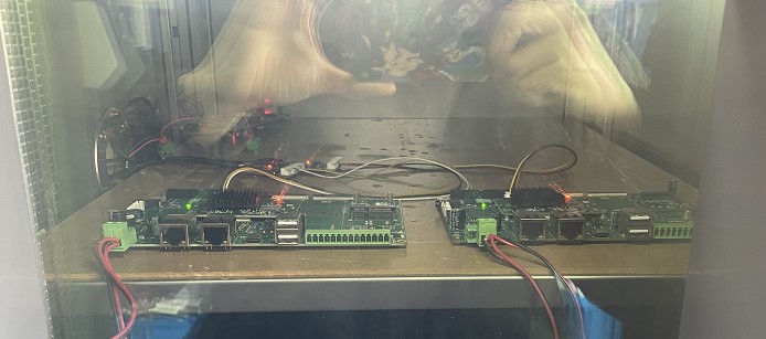
图40?主板环境
? 此时CPU占用率为47%,测得CPU温度为92℃。在85℃高温环境下8小时后,系统未出现死机等情况,正常运行,此时CPU温度为97℃摄氏度,部分数据如图41所示。
At this time, the CPU occupancy rate is 47%, with a CPU temperature of 92°C measured. After 8 hours at a high temperature of 85°C, the system does not have a dead engine, etc., and is functioning normally, at a CPU temperature of 97°C, some of which is shown in figure 41.
?

图41?CPU温度
? 由于篇幅有限,本文仅演示部分数据,全部实际测试结果如表4所示。
Due to space limitations, only some of the data are shown and all the actual tests are shown in table 4.
表4?测试结果
?

? 瑞萨高端MPU平台RZ/G2L有很多可圈可点的地方,例如搭载了双核A55+Cotex-M33处理器,集成高性能Mail-G31?GPU等的核心板,万象奥科评测套件也提供了完善健壮的外设驱动设备支持,还有在不同温度环境下的稳定性能,都给这款开发板加分不少。
The RZ/G2L, a high-end MPU platform in Risa, has a number of niches, such as a dual-nucleic A55+Cotex-M33 processor, the integration of core boards such as high-performance Mail-G31?GPU, which is supported by a robust outer power drive by the Vientiane Oko assessment package, and stability in different temperature environments, all of which add a lot to the development panel.
?

注册有任何问题请添加 微信:MVIP619 拉你进入群

打开微信扫一扫
添加客服
进入交流群


发表评论